Transistors - electrical switches
Table of contents
- what is a diode?
- what is a transistor?
- transistor family tree - and why you’ll likely only need 2 out of all of these
- principle of operation
- designing with FETs
- part selection
- new technologies
- supplementary materials
what is a diode?
- Diodes Summary
- Diodes are the one-way valves of the electronics world and are used everywhere.
- They have a characteristic forward voltage drop, and won’t pass current until it is reached, so not lossless.
- There are a lot of different types of diodes with uses spanning much wider than controlling current direction.
- Silicon diodes are standard when looking at surface mount components, and usually what we mean when we just say “diode.” 0.7 V forward voltage drop is typical.
- Zener diodes allow current to flow in both directions, and so have a (different) forward and reverse voltage drop, which we will discuss exploiting later.
- Schottky diodes can have very low forward voltages (150mV - 450mV) and very fast switching times, so are useful for power electronics circuits. Downsides are comparatively low reverse voltage ratings and high leakage currents.
- LED’s are light emitting diodes, different wavelengths have different V_fs.
- We most often regulate current through an LED with a resistor in series. We can use ohm’s law to size that resistor…
- Using a resistor to limit current is not the most efficient way to accomplish. Later we will talk about DCM.


what is a transistor?
Transistors are electrical switches that can be used to switch on/off higher current loads (anything more than ~10s of mA that you wouldn’t feel comfortable driving off GPIO alone).
They’re 3 terminal devices; whereas 2 terminal devices only have 1 voltage and 1 current, transistors have 2 voltages and 2 currents.

why use one?
Transistors are in everything.
in practice, most use cases that can be handled by discrete transistor circuits will be covered by a specialized IC for that use case (covered more in the other sections).
the major reason to use a discrete transistor is for power switching, which we’ll focus on in this section.
For the rest of this section, we’ll be focusing on Enhancement-mode MOSFETs.
types of transistors
types of transistors
- BJTs - current controlled current sources
- JFETs - non-insulated, voltage controlled current sources
- MOSFETs - insulated voltage controlled current sources
From p71, AoE 3rd Ed: To oversimplify, “BJTs excel in accuracy and low noise, whereas FETs excel in low power, high impedance, and high-current switching; there is, of course, much more to this complex subject.”
From p141 of AoE 3rd Ed: JFETs are well suited to linear applications such as current sources, followers, and amplifiers. A low-noise amplifier with extremely high input impedance, JFETs may be your only friend here.
Compared to BJTs and JFETs, MOSFETs have come to dominate most applications due to their versatility and extremely high input impedance (power efficiency).
some other "types" of FETs
- PRO-fets stand for protected FETs, not P-channel FETs
- not an industry standard term, but used by some manufacturers to describe FETs with built-in protection features like overcurrent, overtmperature, under-voltage lock out (UVLO), short circuit, etc.
- There are a ton of other manufacturer specific names: HEXFET, HITFET, SmartFET, etc.
- if it doesn’t sound familiar, don’t worry; it might just be marketing(tm)
- MOSFETs are sometimes called IGFETs (Insulated-gate FETs)
- this is why MOSFETs have a much higher impedance compared to JFETs, which do not have an insulated gate
transistor family tree - and why you’ll likely only need 2 out of all of these
FETs come in a couple of different flavors:
- gate insulation: MOSFET vs JFET
- polarity: n-channel vs p-channel
- doping: enhancement vs depletion
click here for more on what these words mean
which gate insulation? MOSFET vs JFET
- oxide insulator (MOSFET)
- semiconductor junction (JFET)
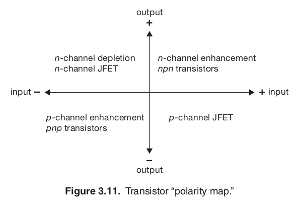
which polarity? N-channel vs P-channel
- N-channel FETs (N-FETs) conduct current using electrons (negative charge carriers).
- P-channel FETs (P-FETs) conduct current using holes (positive charge carriers).
- N-FETs are used more often than P-FETs because electrons have higher charge mobility, leading to lower rds_on and higher efficiency.
how is it doped? enhancement vs depletion
- Enhancement-mode FETs are normally off when V_gs is 0. To turn on:
- N-FET: need to make sure V_gs » V_th
- P-FET: need to make sure V_gs « V_th
- Depletion-mode FETs are normally on when V_gs is 0. To turn off:
- N-FET: need to make sure V_gs « 0
- P-FET: need to make sure V_gs » 0
From p131 of AoE, 3rd Ed: Of the eight resulting possibilities, six could be made, and five actually are. Four of those five are of major importance.
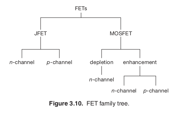
As you can see, there is a combinatorial explosion of FET types given the different ways to build and use FETs.
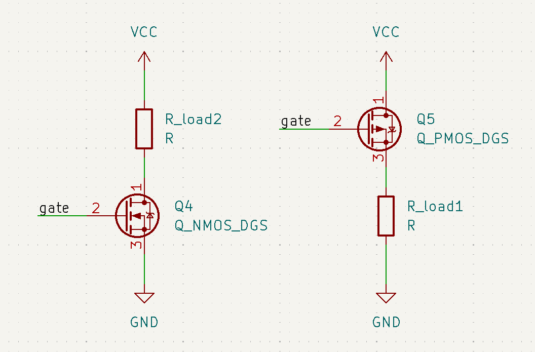
There are a couple of different topologies to implement FETs in, using the following vocabulary.
- High-side FETs are directly connected to the power rail
- Low-side FETs are directly connected to ground
in summary, most applications use N-channel enhancement mode MOSFETs as a low-side switch (easiest/cheapest)
Loads that need to be connected to ground for safety and EMI reasons use P-channel enhancement mode MOSFETs as a high-side switch
click here for more on topology
- https://www.embeddedrelated.com/showarticle/98.php
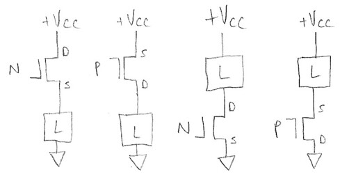
- From left to right, these are:
- High-side switch, N-channel MOSFET
- High-side switch, P-channel MOSFET
- Low-side switch, N-channel MOSFET
- Low-side switch, P-channel MOSFET
principle of operation
- cutoff region - V_gs < V_th
- linear (ohmic) region - V_gs > V_th
- saturation region - V_ds > V_gs - V_th
When using a mosfet as a switch, we are operating in the cutoff and linear regions.
Let’s say we’re using a 5v microcontroller and have a GPIO connected to the gate of our mosfet.
By pulling the gate low, we set v_gs to 0v, and effectively turn off the fet by operating in the cutoff region.
By pulling the gate high, we set v_gs to 5v, and effectively turn on the fet by operating deep in the linear region.
At no point do we enter the saturation region in this operation.
designing with FETs
An excellent overview of how to read a MOSFET datasheet, paraphrased below.
rules of reading a datasheet
- a datasheet is a confident assertion without a legal guarantee (within the datasheet), though there may be a practical guarantee
- to play the Specification Game, you can never exceed the maximum ratings. Otherwise, all bets are off!
- some manufacturers market typical values, some show minimum or maximum
- therefore, unless you have matching conditions, it can be very difficult doing apples to apples comparisons for most specs
- this is also why you should always read the datasheet; digikey listed specs may reflect either typical or min/max values, depending on manufacturer
“Thank you for playing the Specification Game! Remember that marketing summaries don’t matter, typical specifications don’t matter, characterization graphs don’t matter… only the minimum and maximum specifications matter, as long as you meet all the conditions and don’t exceed the Absolute Maximum Ratings.”
important specs
static drain-to-source on-resistance (rds_on) (alternatively, the drive voltage conditions)
- rds on spec normally assumes something like 25 C for junction temp; however, the FET is normally hotter and rds on is normally higher in practice
- (max) rds_on specs usually come with a v_gs and I_d condition
- the v_gs condition is the required “drive voltage” to turn on the FET
- if you cannot exceed the v_gs condition, don’t use the FET! rds_on will typically be higher than spec’d
- for 5V logic systems, shop for 4.5V V_gs conditions
- gate threshold voltage (V_gs(th)) - not useful for turning on FET, important for making sure the device is off
thermal implications - if temperatures are not managed properly, can lead to thermal runaway
- rds_on directly affects power dissipation
- i^2 * r law
- for power fets (1s, 10s of Amps), rds_on becomes a really big deal.
- From p132, AoE 3rd Ed:
- typical power MOSFETs have Rds_on < 0.1 Ω
junction temperature affects rds_on and vice versa
V_ds - drain-to-source breakdown voltage (the max voltage)
this spec is the max voltage the part can see before “all bets are off” it is typical to derate in the 60-70% range
For example, if I have a 48v load that I want to switch, I would look for a fet that has a V_ds rating of at least 48 / 0.6 = 80v.
I_d - current carrying capacity (at temp)
this spec tells you how much current the FET is theoretically capable of carrying. the true current carrying capability depends on how cool you can keep the device, which directly impacts rds_on and therefore power dissipation
Use as a rule of thumb for the load you want to switch, then shop for the lowest rds_on rating you can find using these criteria, as lower rds_on -> lower junction temperature -> more likely you can hit advertised current carrying capabilities.
other important specs
- junction temperature (operating temperature)
- many fets are spec’d to operate up to 150 deg C or 175 deg C
- at the opposite end of the spectrum, fets may have a minimum absolute temperature of -55 deg C, important usually for aerospace only
- gate charge
- useful for figuring out worst case (max) switching times
- which can be important if you need to say, PWM something
- turn-on, rise, turn-off, fall times
- useful for figuring out minimum switching times
application circuits

typical application circuit for a N-channel Enhancement MOSFET operating as a switch for a load
- R_in limits gate current in this instance; gate capacitance can draw significant current when voltage changes quickly
- R_gs: pull-down resistor when FET to make sure gate is not floating
- R_load: thing being powered
- D_flyback: driving inductive loads requires additional protection (collapsing magnetic field could exceed breakdown voltage), requiring a flyback diode in parallel to provide current path
- flyback diode refers to the function of the diode, not the literal construction of diode
- low-speed: use standard rectifier diodes
- high-speed: use fast-recovery or Schottky diodes
- fets have a parasitic body diode from source to drain due to their construction; this confers some protection but may not be entirely adequate for inductive loads
- freewheeling diodes are a similar concept to flyback diodes but used for more complex circuits concerning AC or h-bridges. However, while a flyback diode anticipates and protects against an inductive kickback (voltage spike), a freewheeling diode is designed to prevent a voltage spike in the first place
| Diode Type | Characteristics | Applications |
|---|---|---|
| Schottky Diodes | Low forward voltage drop, fast recovery time | Low voltage, fast switching applications; ideal for low to moderate power levels |
| Fast Recovery Diodes | Designed for fast switching, recovery times in the range of tens to hundreds of nanoseconds | Suitable for applications requiring high-speed switching and moderate to high voltages |
| Ultra-fast Recovery Diodes | Very short recovery time, minimizes energy loss during switching | High-frequency applications where rapid cessation of current flow is critical |
| Standard Recovery Diodes | General-purpose, slower recovery times than fast or ultra-fast diodes | Lower-frequency applications or where the speed of recovery is less critical |
| TVS (Transient Voltage Suppressor) Diodes | Designed to protect against overvoltage transients; very fast response to overvoltage events | Circuits sensitive to high voltage spikes, offering protection by clamping voltage spikes to a safe level |
| Zener Diodes | Can operate in reverse breakdown without damage, used for voltage regulation as well as protection | While not typically used as flyback diodes, can provide overvoltage protection in some circuits by clamping voltage spikes |
schematic symbols and packages (the many varieties)
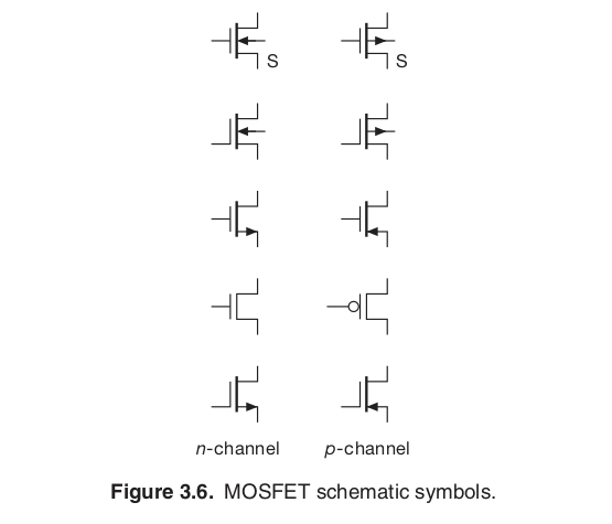
symbols in literature
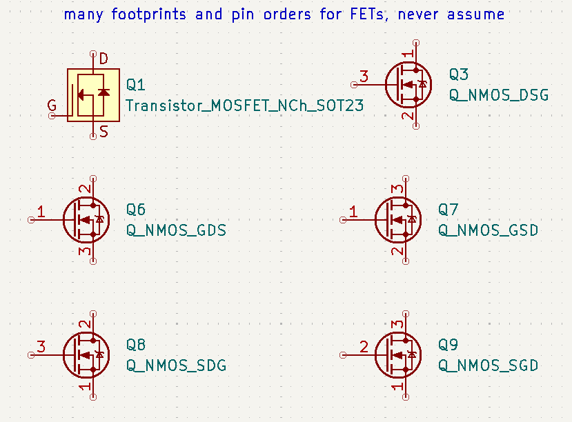
symbols in an ECAD tool like KiCad
- gsd, dgs, dsg
- some symbols have a separate pin for body(?), mostly jfets
- always verify your symbol matches your footprint before sending it out for fab
- selecting packages
- due to thermals, the leadframe of some fets have a large ground pour
- soldering rework can be difficult after installation, plan ahead
part selection
rules of (fet) acquisition - digikey
everything else equal, N-FETs are cheaper/better than P-FETs
listed in this section are some example fets that you can buy, but something even better you can do is go on DigiKey (or Mouser, Arrow, Octopart, etc…) and acquire some yourself!
To start, you’ll most likely want to look under Single FETs, MOSFETs:

I tend to do the following when searching for FETs:
- check “In Stock”
- check “Exclude Marketplace”
- sort price ascending
- Product Status -> Active
- enter 1 in “Pricing Quantity” to get cut-tape instead of reel pricing
Let’s say I chose this example FET:
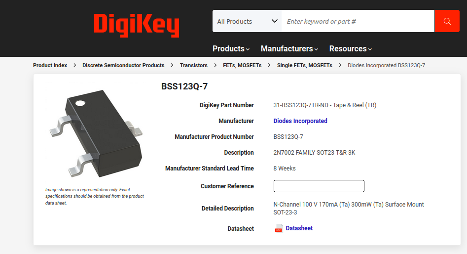
If I click on the datasheet: https://www.diodes.com/assets/Datasheets/BSS123Q.pdf
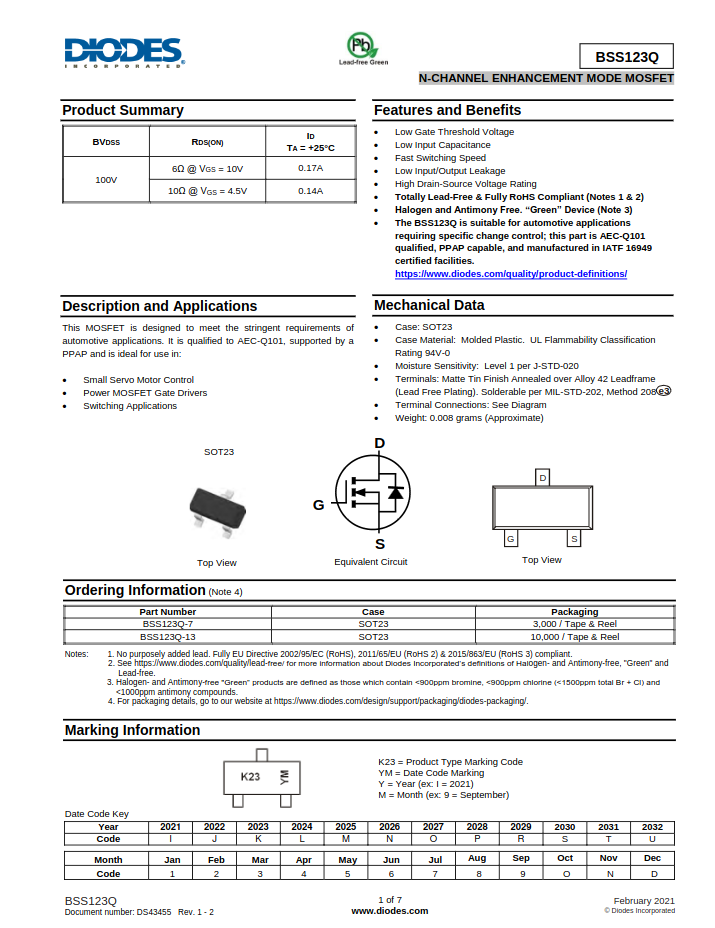
I am greeted by this marketing summary
 immediately I see some useful information about which type of symbol and footprint I should be using in my ECAD design
 if I scroll to the next page, this is followed by max drain-source voltage (V_dss here)
 and further down, I see thermal characteristics, which I can get the operating/storage temperature range.
thermal resistance is also listed here, this information is useful for thermal simulations.
 on the same page under electrical characteristics, note the following drive conditions in particular:

- this tells me that to turn on, I need to meet at least v_gs = 4.5V and to expect at most rds_on = 10 ohms, I_d = 0.17A
- if I increase the drive voltage to at least v_gs = 10V, then the rds_on will only be 6 ohms, so I can expect similar performance but with better thermals
- vgs_th tells me that to make sure I’ve turned off the fet, I need to keep v_gs less than 0.8V
characterization graphs
keep in mind again, these are graphs of typical behavior and should not be applied literally to FETs, but taken as a qualitative measure of their behavior (exception is the SOA graph)
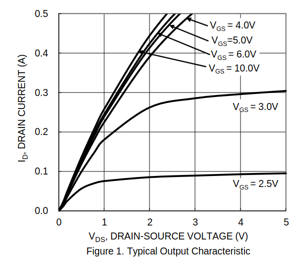 I_d vs v_ds; this graph shows where the operational regions (cutoff, linear/ohmic, and saturation) exist. Recall that as a switch, the FET should be operated in cutoff for off, and linear/ohmic for on. It should not be in the saturation region.
This representative graph better demonstrates where these regions exist: 
and here’s a graph from another datasheet that better demonstrates how behavior changes at higher temperatures (25 deg C vs 175 deg C): 
 rds_on vs T_j; essentially rds_on increases as temperature increases, and thermal runaway can happen if thermals are not properly managed
 I_d vs v_ds, Safe Operation Area (SOA); this graph can be taken literally and shows where it’s safe to operate the FET as a function of the current, drain-to-source voltage, and frequency of operation.
- this is useful for understanding how long I can have the fet on, and how to keep it safe from faults
- for example, I can have the FET operate statically with I_d = 20mA and v_ds = 0.2v, but if I want to pass a pulse of 400mA, I can only do it if I increase v_ds to 2v and only pass a pulse that lasts up to 100ms
- another way to think about this is if a fault occurs in my system that passes 400mA at 2v, I have 100ms to shut-off the FET before it sees permanent damage
gate drivers
Although logic-level fets can be driven directly by GPIO (digital high is enough to satisfy drive voltage), if you care about switching speed you’ll likely need a gate driver.
In fact, standard power fets typically require a gate driver, as their drive voltages are normally 10v or higher.
GPIO can typically supply some 10-20 mA, but gate drivers can supply much higher current, which is needed to quickly charge and discharge the gate, which switches the fet.
Gate driver ICs are commonly used alongside discrete fets and can also be found on sites like digikey.
fet tables
Some FETs selected by size:
| Package | Dimensions | Link | Breakdown Voltage | Continuous Drain Current | Max Power Dissipation | Mount Type |
|---|---|---|---|---|---|---|
| SOT-23 | 3.04x2.64 mm | Vishay Siliconix SI2336DS-T1-GE3 | 30 V | 5.2A (Tc) | 1.25W (Ta), 1.8W (Tc) | Surface Mount |
| SOT-323 | 2.2x2.45 mm | Diodes Incorporated DMG1012UW-7 | 20 V | 1A (Ta) | 290mW (Ta) | Surface Mount |
| SOT-416 | 1.6x1.6 mm | ON Semiconductor NTA4153NT1G | 20 V | 915mA (Ta) | 300mW (Tj) | Surface Mount |
| SOT-723 | 1.2x1.2 mm | ON Semiconductor NTK3134NT5G | 20 V | 750mA (Ta) | 310mW (Ta) | Surface Mount |
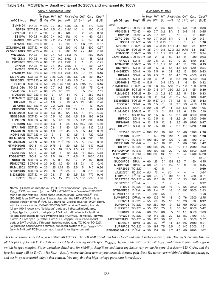
p188 of Art of Electronics, 3rd Ed has 4 pages worth of nMOS and pMOS FET parts you can find off digikey as well, here’s the first page:
new technologies
| Technology | Voltage Range | Current Capacity | Efficiency & Performance Characteristics |
|---|---|---|---|
| IGBT | ~1000s of V | 10s to 100s of A | Better efficiency at high voltages and currents, slower switching speeds compared to MOSFETs. |
| SiC | ~1700 V or more | Comparable to silicon | Higher temperature, voltage, and frequency operation than silicon. Lower on-resistance, higher thermal conductivity. |
| GaN | Up to ~600 V | Comparable to silicon | Higher efficiency due to faster switching, lower on-resistance than silicon, higher power density. |
| MOSFETs | Up to 600-900 V | Depends on the device | Lower voltage and current handling compared to IGBTs and SiC, less efficient at high power compared to GaN and SiC. |
IGBTs (Insulated Gate Bipolar Transistors)
- IGBTs combine the easy control of MOSFETs with the high current and low saturation voltage of bipolar transistors
- compared to MOSFETs, IGBTs offer better efficiency at high voltages and currents but have slower switching speeds
SiC (Silicon Carbide)
- SiC devices can operate at higher temperatures, voltages, and frequencies than silicon-based devices
- SiC MOSFETs, have improved efficiency due to lower on-resistance and higher thermal conductivity
- smaller, lighter, and more efficient power systems than traditional silicon devices
GaN (Gallium Nitride)
- GaN transistors excel in high-frequency and high-efficiency applications, capable of operating at higher temperatures and voltages than traditional silicon MOSFETs
- switch on and off much faster, reducing energy loss and improving efficiency
Relays vs Solid-State Relays
- relays are electro-mechanical devices that are actuated using electromagnetic fields to mechanically close a contact switch
- cons: slow, less resilient to shock and vibe, arcing
- in comparison, solid-state relays are typically much faster, and due to isolation strategies are not susceptible to arcing, and due to solid-state more resilient to shock and vibe
- https://www.arrow.com/en/research-and-events/articles/crydom-solid-state-relays-vs-electromechanical-relays
- there are many topologies that SSRs can be implemented in
- Optocoupled SSRs
- Transformer Isolated SSRs
- Triac-based SSRs
- MOSFET-based SSRs
- IGBT-based SSRs
- Zero Crossing SSRs
- Analog Switching SSRs
supplementary materials
- art of electronics, 3rd ed chapter 3
- links
- https://www.embeddedrelated.com/showarticle/809.php
- IR AN1084 Power MOSFET Basics
- IR AN936 The Do’s and Don’ts of Using MOS-Gated Transistors
- IR AN937 Gate Drive Characteristics and Requirements for HEXFET® Power MOSFETs
- IR AN941 Paralleling Power MOSFETs
- IR AN944 Use Gate Charge to Design the Gate Drive Circuit for Power MOSFETs and IGBTs
- IR AN947 Understanding HEXFET® Switching Performance
- IR AN949 Current Ratings of Power Semiconductors and Thermal Design
- IR AN957 Measuring HEXFET® MOSFET Characteristics
- IR AN976 Understanding and Using Power MOSFET Reliability Data
- IR AN1005 Power MOSFET Avalanche Design Guidelines
- IR AN1012 Mounting Considerations for International Rectifier’s Power Semiconductor Packages
- IR AN1040 System Simulation Using Power MOSFET Quasi-Dynamic Model
- Fairchild AN558 Introduction to Power MOSFETs and their Applications
- https://www.embeddedrelated.com/showarticle/98.php
- https://www.embeddedrelated.com/showarticle/809.php