Drivers
Table of contents
Definition
In general, a driver is a device that serves as an interface between a microcontroller and an output device.
Here, we will focus on motor drivers, as each type of motor is an interesting case study that requires a specific flavor of driver.
Half bridge
A half-bridge uses two transistors to drive load to a high or a low voltage, on command:
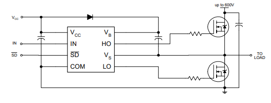
Note that when using an N-channel MOSFET on the high side, the gate needs to be set to the load’s voltage, plus what’s needed to trigger switch the transistor. This requires a specific gate driving scheme called bootstrapping.
H-bridge
A single power transistor can be used to modulate the amount of current sent to a load (like a DC motor), but the direction of the current can’t be flipped.
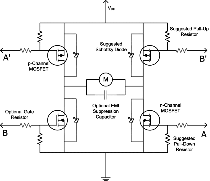
An H-bridge is a neat configuration of 4 power transistors that can be used jointly to send current to a load in one direction or the other.
Here’s an example of an H-bridge built from 2 N-channel and 2 P-channel MOSFETs:
Here’s a table of operation, varying the :
| A | B | A’ | B’ | Outcome |
|---|---|---|---|---|
| H | L | L | H | Motor moves right |
| L | H | H | L | Motor moves left |
| H | H | H | H | Motor brakes |
| L | L | L | L | Motor brakes |
| L | L | H | H | Motor coasts (open) |
| L | H | L | H | Forbidden (short) |
| H | L | H | L | Forbidden (short) |
To avoid dealing with this table and risking entering a short circuit condition, it is common to use an IC that includes a logic controller. In that case, the user is presented with only two inputs, and a simplified table. Here is a an example taken from the TB67H451F’s datasheet:

Current control
A common scheme for modulating the current on a load is to simply chop the voltage being sent to it. The instantaneous current is measured with a shunt resistor, and the power gets commutated based on the result (higher or lower than the target current).
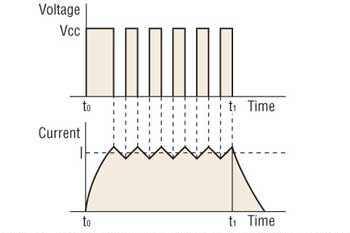
This usually happens at tens of KHz, making it unnoticeable as it gets dampened by the mechanical system being driven.
Motor drivers
Brushed DC motor
A DC motor is commonly driven by a single H-bridge with current sensing:

Note the Rs shunt resistor, and the Vref input. The logic controller compares the induced voltage on Rs (usually multiplied by a gain of e.g. 10) with the voltage reference, and chops accordingly.
Back emf sensing
As the emf is approximately proportional to the DC motor’s speed, basic speed control can be achieved by estimating the emf.
Stepper
Bipolar steppers have two sets of coil, which can each be driven by an H-bridge:
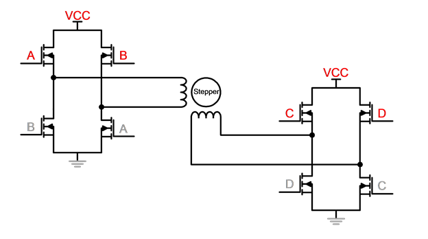
Full-step motion involves flipping the current on the two H-bridges in the following sequence:
| H-bridge 1 | H-bridge 2 |
|---|---|
| + | − |
| + | + |
| − | + |
| − | − |
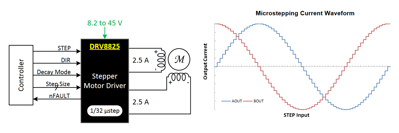
For microstepping, PWM modulation on the two H-bridges is used to create “in-between” states:

To avoid dealing with the PWM modulation, it’s common to use an integrated stepper driver, which takes step and direction signals and takes care of the rest:
Jake made a good reference dual H-bridge driver here: https://modular-things.com/things/stepper-hbridge-xiao/
Sensorless homing
Some modern stepper drivers can achieve stalling detection by measuring changes in the back emf. The back emf can be measured once/twice per commutation cycle: when the current being sent to a set of coil is =0, that set can be used as a sensor.
The Prusa MK3 and MK4 rely on the TMC’s stall detector to reliably achieve sensorless homing.
BLDC
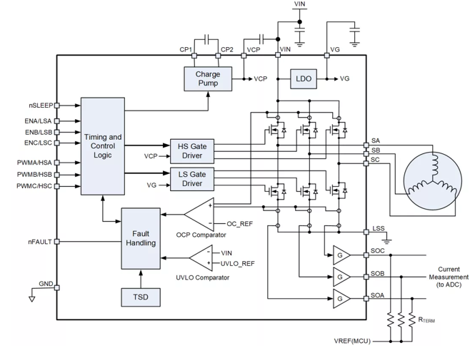
A BLDC in a star configuration requires current control in the three sets of coils, which can be achieved with 3 half bridges:
Trapezoidal commutation is the easiest (blind start) and implemented on most hobby ESCs:

FOC is a more sophisticated commutation scheme requiring knowledge of motor angle. It creates a uniform rotating magnetic space vector, by applying PWM on the phases. Its advantages are:
- High power output
- Low noise
- Low torque ripple
- Higher speed (field weakening)
- Max motor efficiency
Angle feedback can either be done with Hall effect sensors, or by measuring the back emf on the winding that’s currently undriven (“sensorless” control):

In either case, controlling torque at zero speed or doing fine position control is not easy with sensorless schemes.

The basic idea is to sense the back-emf and build an observer to estimate the motor state (angle, velocity, etc.).
Here’s a reference for further reading: https://www.ti.com/video/6216805428001