Regulators
Table of contents
linear and switching regulators
There are two broad catergories of regulators: linear and switching. The upside of linear regulators is simplicity. At low power they work just fine with the added benefit of having no switching noise and ripple. If you want to transfer substantial power and with reasonable efficiency then you will need to use a switching regulator. The regulators we discuss here are DC-DC converters.
linear regulator examples
A few common designs include
- voltage divider + buffer (emitter follower for instance)
- LDO (low-dropout regulator)
- Zener reference
Most linear regulators only step down in voltage. The voltage divider is not a good regulator unless followed by a buffer (typically a power amp if you need to supply substantial current). LDO’s and Zener references can be more stable and efficient.
The mechanism of an LDO is to servo a “pass element” to set an output voltage. See this Q&A from Analog Devices on LDOs or this other app note.

A good linear regulator design will use all the tricks to squeeze out efficiency and provide stability through feedback.

A good place to start is TI’s page on LDO’s or Chapter 9 of AOE Horowitz & Hill 3rd Edition.
Another key application of linear regulators is when one needs a precision rail. See for instance, these high precision voltage references made by Apex Microtechnology.
switching regulator examples
There are a myriad of topologies for switching DC-DC converters. To give an idea, here is a non-exhaustive list:
- Buck $D$
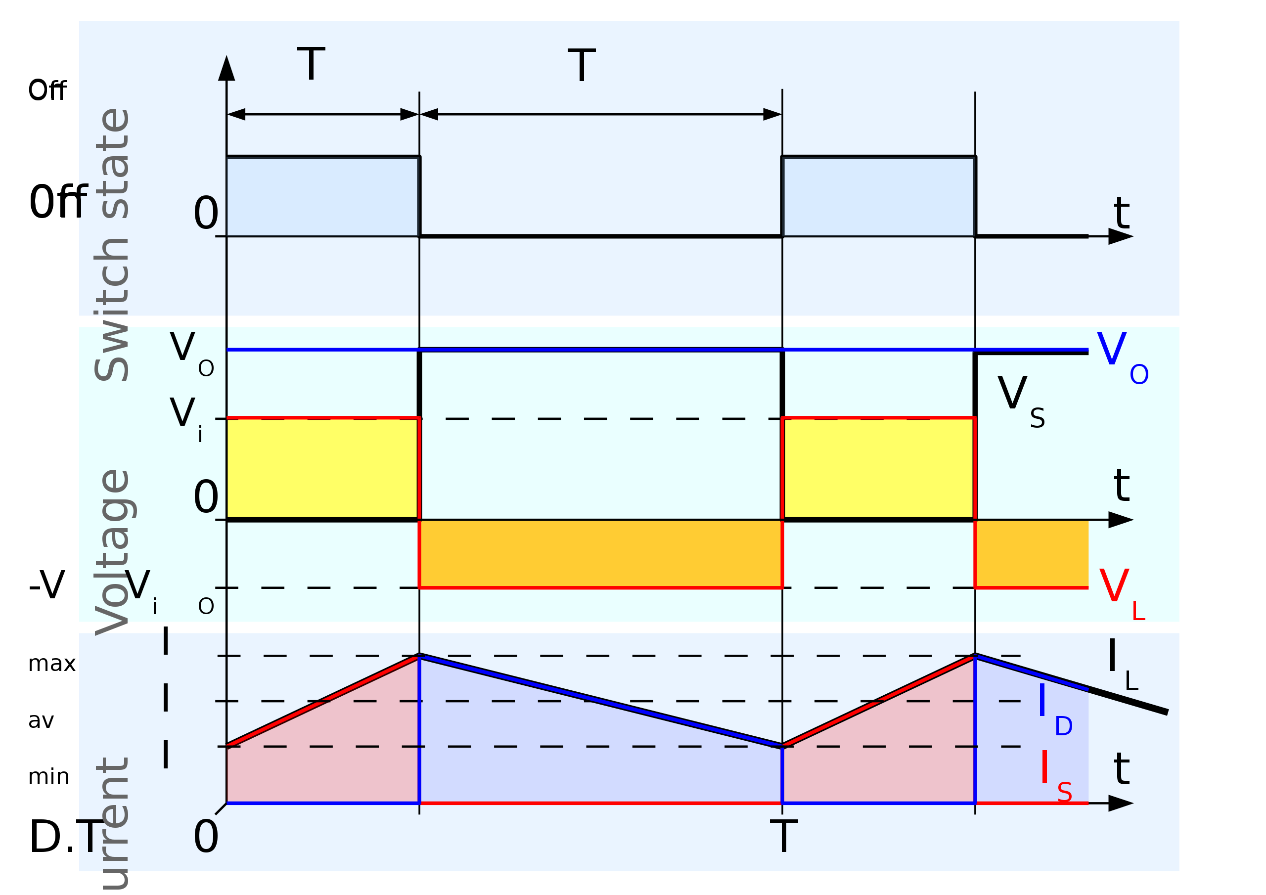
- Boost $\frac{1}{1-D}$
- Buck-Boost $\frac{D}{1-D}$
- Flyback $\frac{N_s}{N_p}\frac{D}{1-D}$
- Forward
- Zeta
- Cuk
- Landsman
- SEPIC
- Switched capacitor
- Resonant converters
- etc.

Recommend 6.334 (G) Power Electronics and 6.332 (G) Advanced Power Electronics. Some inverter topologies (boost, flyback) can produce higher output voltages than input. However, in all cases, conservation of energy/power must hold.
What’s with all these topologies!
Landsman showed in 1979 that you can derive all the major DC-DC converters by different connections of a canonical cell. There are also several interesting ideas in network theory that predict certain topologies. For instance, there are methods to create topological duals. The topological dual of a voltage doubler is a current doubler!
Converter analysis (forthcoming)
The way these switch mode converters work is by driving transistors as switches using PWM. In the analysis, we often simplify and assume the the switches are ideal. The analysis of these converters is far more nuanced and we will omit many details like switching loss, discontinuous vs continuous conduction mode, deadtime to prevent shoot through, floating gate drives, current and voltage ripple, feedback, etc.
To figure out how duty cycle $D$ of PWM relates to output voltage, we use the method of assumed states (cf. any power electronics text, e.g., KPSV or Erickson & Maksimović).
We summarize a few examples here.
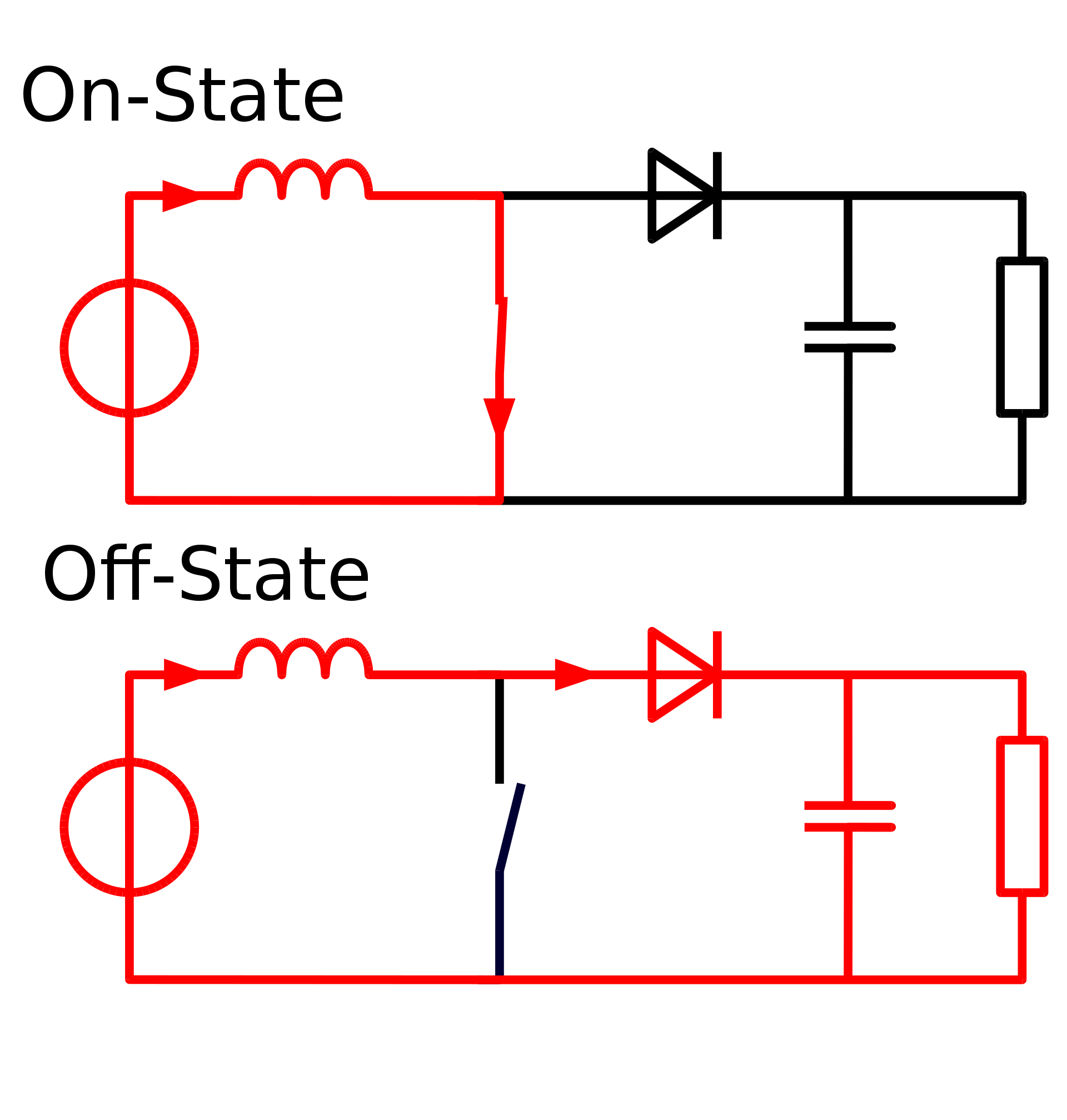
Always put a load on the output of your boost converter!